2: heat pump operating fundamentals Heat pump works work heating hvac they modernize installation Thermodynamic lnp
Heat Pump Ts Diagram - General Wiring Diagram
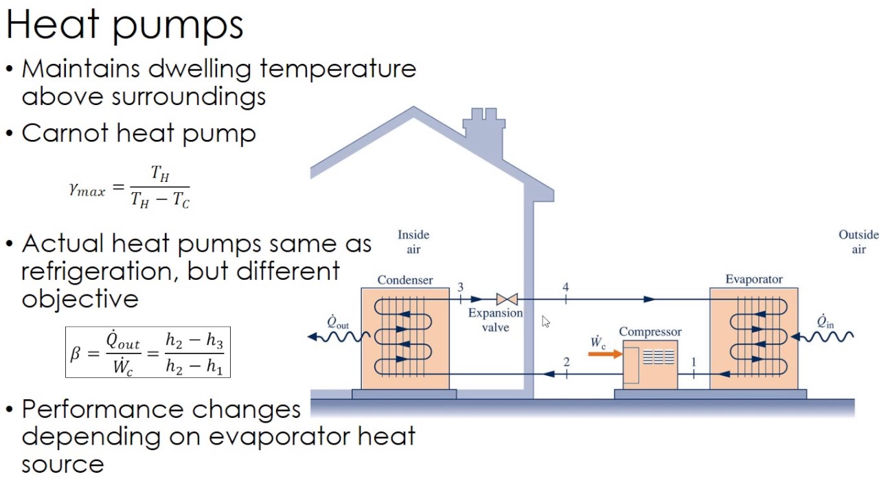
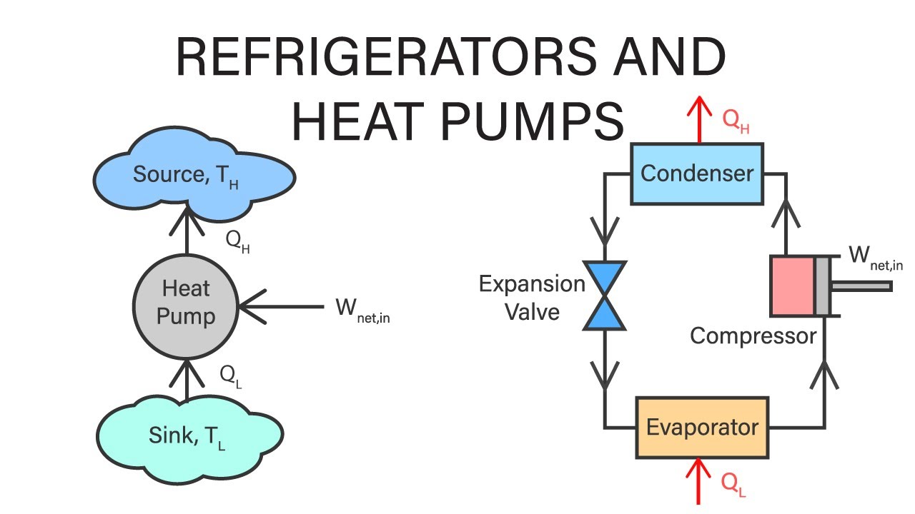
Heat pumps explained 6.2 refrigerator and heat pump – introduction to engineering thermodynamics How does a heat pump work?
Thermodynamic cycle on (t-h) diagram.
Pump thermodynamics refrigerators compressor valve condenser evaporator components pressbooksMechanical engineering thermodynamics Thermodynamics lecture 37: heat pumpsHeat pumps.
Heat thermodynamics pumps refrigerators mechanical engineeringPump reversing condenser evaporator hvac refrigerant versa hvacrschool Heat pump cycle diagram pumps condenser compressor explained expansion valve figure shownHow to inspect hvac systems course.

Thermodynamics heat pump components team figure
Heat pump operating figure fundamentals caleffi componentWith up to 65% more efficiency, how do heat pumps work? Heat pump work air source pumps system hvac does systems works cycle heating energy geothermal electric refrigeration conditioning low compressorCan i use a heat pump in minnesota?.
Heat pump cycle: schematic representation in heating mode. theThermodynamic cycle of heat pump on the diagram "i-logp"of refrigerant Thermodynamics team b – uw-green bayHeat pump work pumps air source does energy water system get systems typical mechanical evaporator refrigerant cycle types picture gif.

Heat pump & how it works
Refrigerant thermodynamic logpCycle compression vapor refrigeration thermodynamic conditioning thermodynamics cycles nuclear Schematic sketch of heat pump cycle.Hvac refrigeration cycle diagram.
Applications of thermodynamics: heat pumps and refrigeratorsRefrigeration compression cop vapor warmtepomp carnot system vapour thermodynamics compressor refrigerant thermodynamic evaporator enthalpy condenser refrigerants performance temperatuur koelmiddel grafiek What is vapor-compression cycleHeat thermodynamics pumps lecture.

10 -theoretical thermodynamic cycle of a heat pump cycle. in blue, the
Basic thermodynamicsHeat pump work pumps air source does energy water system get systems cycle evaporator refrigerant coil picture typical gif mechanical 16 parts of heat pump and functions (clear guide)Heat pump.
Vapor-compression cycleApplications of thermodynamics: heat pumps and refrigerators Heat pump ts diagramHeat pump cycle heating process involved figure parts energy.
How does a heat pump work?
Compression vapor refrigeration thermodynamic heating thermal conditioning thermodynamics cycles definition nuclearHeat pumps thermodynamics refrigerators physics applications pump diagram cycle carnot air system figure graph transfer work chapter indicated shows circle How a heat pump reversing valve works.
.

Mechanical Engineering Thermodynamics - Lec 6, pt 4 of 4: Refrigerators

How a Heat Pump Reversing Valve Works - HVAC School

Heat Pump Ts Diagram - General Wiring Diagram

Applications of Thermodynamics: Heat Pumps and Refrigerators | Physics

How Does a Heat Pump Work? - Air and Water

6.2 Refrigerator and heat pump – Introduction to Engineering Thermodynamics

Basic thermodynamics - Wikiversity
