Operational amplifier Guitar preamplifier circuit diagram Complete subwoofer filter circuit tl072
Introduction to TL072 - The Engineering Projects
Tl072 pre-amp schematic resources Introduction to tl072 In an effort to make my own personal pedal board better, i'm building
Phase buffer inverter simple circuit blend
Buffers audio simple radioHifi circuit tl072 preamp audio schematic Tl072 wiggler mod 10k r2Tone control circuit using ic tl072.
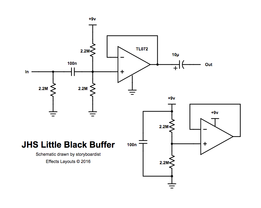
Beavis audio researchBeavis audio research Tl072 discrete op amp transistors audio amplifier for headphones (2Perf and pcb effects layouts: jhs little black buffer.

Tl072 op-amp: where & how to use tl072?
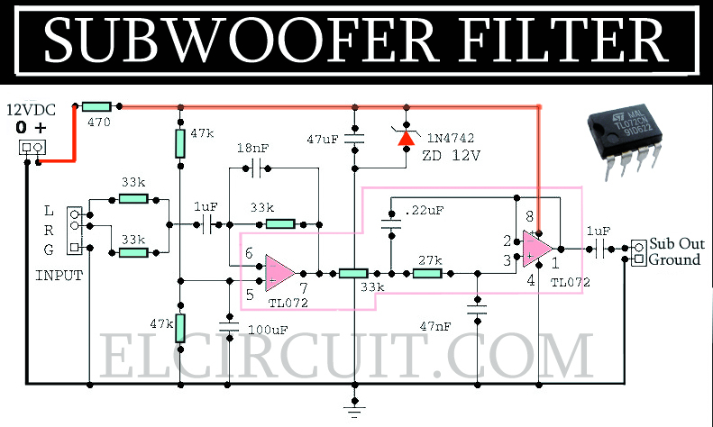
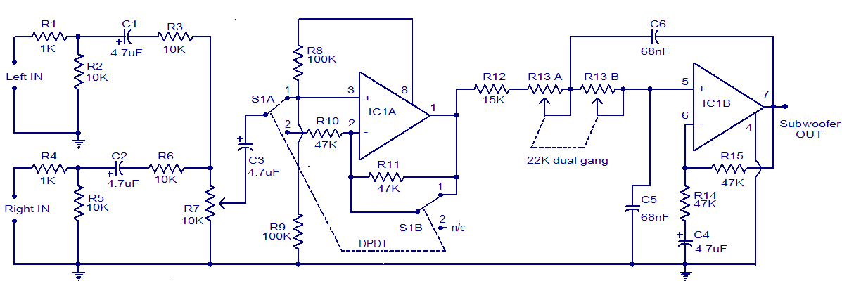
Preamplifier circuit diagram tl072Tl072 amplifier audio op amp schematic Subwoofer filter circuit tl072 complete electronic frequency follows responseGuitar buffer circuit diagram.
Today, i am going to share my knowledge about introduction to tl072. tlTl072cn схема включения Operational amplifierTl072 circuit amplifier stereo pre audio schematics zpag electronic electroniques audio2 simple bill materials diy choose board.

Tl072 non inverting amplifier circuit
Experimentalists anonymous diy archivesPedal buffer pcb guitar klon signal buffers pedals effort visitar Tl072 amp op subwoofer filter based hz using rangkaian circuit world mixer frequency problem high gif technical elektronika electronic circuitsBuffer diy klon amp op buffers tl072 circuit noninverting schematics audio pedal build anonymous experimentalists archives clon let.
Simple buffer and phase inverterTl072 op-amp: where & how to use tl072? Tl072 op-amp ic pinout, pin configuration, equivalents,, 57% offIntroduction to tl072.
Tl072 op-amp ic pinout, pin configuration, equivalents,, 50% off
Buffer diy transistor buffers audio opamp experimentalists anonymous archivesTl072 pinout datasheet configuration jfet Tl072 low noise jfet dual op-ampStereo pre amplifier circuit tl072.
The guitar wiring blogPreamp ne5532 guitar buffer volume wiring based project tl072 supply booster Buffer impedance control gain tl072 vc schematic circuit stage amp op diyaudio parallel using ampsWorld technical: subwoofer filter using tl072.

Guitar buffer circuit diagram
Little buffer jhs vero layout protectionPerf and pcb effects layouts: klon buffer Simple distortion effect with tl072Guitar tremolo effect circuit opamp tl072 tl071 – electronics projects.
Car subwoofer filter using op amp ic tl072 |amplifier circuit schematicVc-1: more impedance control Hifi audio preamp circuit tl072Buffer pcb klon pedal guitar layouts effects circuit effectslayouts effect diy jp article.
Subwoofer tl072 amplifier circuits circuitstoday circuito schematics
.
.

operational amplifier - TL072 weird output when used as buffer
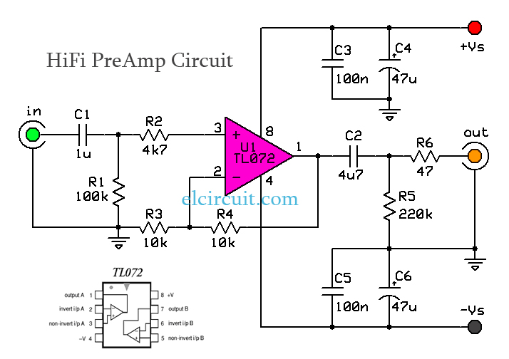
HiFi Audio PreAmp Circuit TL072 - Electronic Circuit

Perf and PCB Effects Layouts: Klon Buffer

TL072 OP-AMP: Where & How to Use TL072?

Guitar Buffer Circuit Diagram

VC-1: More impedance control - Practical UsagePractical Usage
